

Choosing the right line filters for global sourcing requires more than comparing prices and catalog pictures. These components protect equipment from conducted electromagnetic interference, unstable power, and unwanted electrical noise. A filter that performs well in a clean laboratory may fail near welders, variable-frequency drives, or crowded production lines. Context matters.
Start with the equipment’s voltage, current, frequency, impedance, and operating environment. Check insertion-loss data across the actual noise spectrum, not only one attractive test point. Temperature, humidity, vibration, and enclosure space also affect long-term performance. Small details matter. A 10-amp filter may overheat when the application draws continuous current near its rating.
Reliable sourcing depends on verifiable evidence. Request datasheets, test reports, traceable certificates, and samples from qualified manufacturers. Confirm compliance with applicable regional requirements, such as electromagnetic compatibility and safety standards. Do not treat a supplier’s “international quality” statement as proof. Independent testing or an accredited laboratory can provide stronger assurance.
Practical evaluation should include a pilot order and inspection plan. Measure dimensions, terminals, leakage current, dielectric strength, and attenuation before approving mass production. Inspect packaging too; damaged terminals can create field failures long after shipment. I have found that documentation is often less consistent than the product itself, so every specification deserves confirmation.
No checklist is perfect. Supplier capacity, component substitutions, and changing regulations can introduce risks after approval. Build communication checkpoints into the purchasing process, and review performance data after installation. The best line filters balance electrical performance, safety, availability, and total ownership cost. That balance may require revising an early decision.
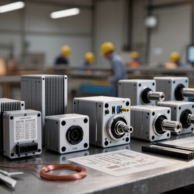
Line filters reduce unwanted electrical noise before it reaches equipment or the power network. Their design starts with the noise type. Common-mode noise travels on line and neutral in the same direction. A common-mode choke creates opposing magnetic fields for normal current, but high impedance for shared interference. Differential-mode noise moves between conductors. X capacitors and series inductors suppress this path. Y capacitors connect conductors to protective earth, controlling common-mode noise while limiting leakage current.
The filter type must match the circuit. Single-phase equipment often uses an LC network with one choke, one X capacitor, and two Y capacitors. Three-phase systems need coordinated filtering across all phases. Feedthrough filters suit compact, high-frequency applications. Their short current path can improve insertion loss.
However, “more filtering” is not always safer. Excess capacitance may increase leakage current, while an undersized choke can overheat during inrush.
MarketsandMarkets reported continued growth in the global EMI shielding market, driven by denser electronics and stricter electromagnetic compatibility requirements. Its 2024 analysis projected the market to expand from about 6.8 billion dollars in 2023 to roughly 9.1 billion dollars by 2028.
Sourcing teams should compare insertion-loss curves, rated voltage, current, temperature, dielectric strength, and leakage limits. IEC 60939 requirements provide a useful verification framework.
A perfect curve on paper can still fail in a noisy cabinet. I have seen selection decisions rely too heavily on one test frequency. That is a mistake worth revisiting. Filter performance depends on wiring length, grounding, enclosure geometry, and the actual load.

How to Choose the Right Line Filters for Global Sourcing
Assess Voltage, Current, Frequency, and Environmental Requirements
Choosing a line filter starts with the equipment’s actual electrical conditions, not its appearance. Read the nameplate carefully. Confirm nominal voltage, maximum voltage, and possible transient exposure. A 240-volt system may experience short spikes during switching. The filter must tolerate them safely.
Current deserves equal attention. Estimate the continuous load, then check startup demand from motors, compressors, or power supplies. A modest operating margin is useful. Excessive margin, however, can increase cost and reduce practical filtering performance. Frequency also matters. Many filters support 50 or 60 hertz, but not every design performs equally across both systems. Verify insertion-loss data at the required frequency. Do not rely only on a broad datasheet statement. This is often overlooked.
Environmental conditions can change the selection completely. Consider temperature, humidity, dust, vibration, altitude, and available enclosure space. A filter used near a production line may need stronger mechanical protection than one installed in a clean cabinet. In humid storage areas, moisture resistance becomes important. Confirm terminal materials and insulation ratings, too. During sourcing reviews, record each requirement in a comparison sheet. I once treated enclosure size as a minor detail. That mistake caused unnecessary redesign work. A filter that fits electrically may still fail during installation.
| Application Type | Typical Supply Voltage | Typical Current Range | Power-System Frequency | Recommended Filter Configuration | Typical Operating Temperature | Environmental and Installation Requirements | Key Selection Checks |
|---|---|---|---|---|---|---|---|
| Single-phase commercial equipment | 100–120 V AC or 220–240 V AC | 1–16 A | 50 or 60 Hz | Two-line EMI filter with common-mode choke, X capacitor, and Y capacitors | −25°C to +85°C | Indoor equipment, pollution degree 2, non-condensing humidity; provide protective earth where required | Confirm rated voltage, continuous RMS current, leakage current, terminal arrangement, and safety approvals for the destination market |
| Three-phase industrial machinery | 380–415 V AC or 440–480 V AC line-to-line | 10–100 A | 50 or 60 Hz | Three-phase, three-line or four-line filter; use a neutral conductor only when required by the system | −25°C to +70°C | Industrial cabinet, vibration, dust, and elevated ambient temperature; maintain short, low-impedance protective-earth connections | Check phase configuration, prospective short-circuit current, overload capability, heat dissipation, and enclosure rating |
| Variable-frequency drive or motor controller | 200–240 V AC or 380–480 V AC | 5–60 A | 50 or 60 Hz input; high-frequency switching noise at the output | Input EMC filter; use a motor-output filter only when the drive and motor-cable installation require it | −10°C to +50°C without derating in many installations | Use shielded cables, 360-degree shield termination where applicable, and separation between power and control wiring | Verify compatibility with switching frequency, motor-cable length, leakage-current limits, and drive manufacturer requirements |
| Switch-mode power supply input | 90–264 V AC universal input | 0.5–5 A | 47–63 Hz | Compact single-phase EMI filter designed for differential-mode and common-mode noise | −25°C to +85°C | Suitable for enclosed electronic equipment; consider airflow, inrush current, and capacitor aging at high temperature | Ensure the filter current rating exceeds maximum input current, including startup conditions and low-line operation |
| Low-voltage DC control equipment | 12 V, 24 V, 36 V, or 48 V DC | 1–30 A | DC; switching noise commonly ranges from tens of kHz to several MHz | DC feed-through filter or common-mode choke with appropriate differential-mode capacitance | −40°C to +85°C | Automotive, telecom, or control-panel environments may require vibration, reverse-polarity, and transient protection | Do not use AC-rated capacitors without confirming DC suitability; check polarity, ripple current, voltage derating, and grounding method |
| Medical electrical equipment | 100–240 V AC, depending on the intended market | 1–10 A | 50 or 60 Hz | Medical-grade filter with controlled leakage current and suitable insulation system | 0°C to +40°C is common for equipment used in controlled indoor areas | Patient-connected applications require particular attention to leakage current, creepage, clearance, and protective-earth integrity | Select against the applicable medical-equipment standard and verify normal, single-fault, dielectric-strength, and leakage-current performance |
| Outdoor or harsh-environment equipment | 120 V AC, 230 V AC, or 400–480 V AC | 2–40 A | 50 or 60 Hz | Sealed or coated filter assembly with surge protection selected separately or integrated where appropriate | −40°C to +85°C, subject to component and enclosure limits | Consider condensation, salt mist, UV exposure, dust, water ingress, altitude, vibration, and corrosion-resistant terminals | Check enclosure protection level, climate category, surge environment, creepage distance, and current derating at high ambient temperature |
A suitable line filter must perform under real operating conditions, not only in a laboratory table. Compare insertion loss across the required frequency range, rated voltage, current capacity, leakage current, and temperature limits. Ask for test curves at the actual load. A filter may show impressive attenuation at one frequency but perform poorly elsewhere. I once trusted a single headline figure and missed a resonance issue during system testing. That mistake was preventable.
Compliance evidence should match the destination market and the finished equipment. Request safety reports, electromagnetic compatibility test results, material declarations, and production traceability records. Check whether testing covered the complete filter assembly, including terminals, housing, and grounding details. Supplier certifications also need careful review. An ISO 9001 certificate supports process control, but it does not prove product performance. Confirm the certificate number, scope, validity, and issuing body. Independent laboratory reports are stronger when they identify the exact model and test conditions.
Tips: Compare samples from at least two production lots. Inspect markings, dimensions, wiring, and packaging. Ask how failed units are isolated and recorded. Request change-notification procedures for materials or factories. Do not accept copied reports without verification. A supplier may answer quickly, yet provide incomplete evidence. Leave room for doubt. Verify everything important.
When sourcing line filters internationally, compare the complete landed cost, not only the quoted unit price. Include tooling, inspection, packaging, freight, duties, and payment fees. A filter priced two dollars lower may cost more after air freight and rework. Request cost breakdowns from each supplier. Then test the assumptions against recent shipping invoices.
Lead time needs a practical definition. Ask about sample approval, production, port handling, customs clearance, and inland delivery. A supplier promising 18 days may still require six weeks at your warehouse. Use a timeline with actual dates. For example, reserve 10 days for inspection and 14 days for ocean transport. Weather and port congestion can still disrupt this estimate. Build a modest buffer.
Reliability depends on evidence, not confident emails. Review inspection records, batch traceability, failure rates, and corrective-action history. Check whether the supplier can maintain filtration efficiency across repeated production runs. Order a pilot batch and measure pressure drop, dimensions, and seal quality. Keep retained samples for comparison. This costs time. It can prevent expensive line stoppages. I have found that supplier scoring often looks precise, while its data is incomplete. Recheck the score after each shipment, and reduce dependency when one factory controls the entire supply. Ask difficult questions early.
Selecting a line filter supplier starts with the application, not the catalogue. Define voltage, current, frequency, leakage-current limits, and enclosure space. Then request insertion-loss curves across the actual operating range. A filter that performs well at 150 kHz may weaken near 30 MHz. Small details matter.
Test samples under realistic conditions. Measure common-mode and differential-mode attenuation, dielectric strength, insulation resistance, temperature rise, and leakage current. Repeat tests after vibration and thermal cycling. IEC 60939 provides a useful framework for passive filter safety and performance. The 2024 EMC Filters Market report by MarketsandMarkets projects continued market growth through 2029, increasing the need for consistent qualification rather than attractive pricing alone.
Audit the supplier’s process before approving production. Review material traceability, incoming inspection, winding controls, calibration records, and change-notification procedures. Ask for capability data, failure analysis, and samples from different production lots. A supplier should explain how ferrite cores, capacitors, terminals, and housings are controlled. I have seen excellent laboratory samples fail after assembly changes. That risk is easy to underestimate. Deloitte’s 2023 Global Chief Procurement Officer Survey reported that supply resilience remains a major procurement priority, so evaluate capacity, alternate materials, lead times, and recovery plans.
No scorecard is perfect. Keep one open question: what evidence would change our decision?