

A butterfly valve is a compact quarter-turn device that controls fluid flow through a pipe. Its central disc rotates around a stem, opening the passage, restricting it, or stopping it. The mechanism is simple. Its consequences are not.
Industry reports show why this design remains relevant. Grand View Research’s Industrial Valves Market report identifies water and wastewater treatment, oil and gas, chemicals, and power generation as major demand sectors. MarketsandMarkets also projects continuing growth in the global industrial valves market, driven by infrastructure renewal and process automation. These reports do not measure every butterfly valve separately, but they reveal the industrial conditions supporting its use. Demand is especially visible where large pipe diameters require low weight, fast operation, and manageable maintenance.
In practical service, an operator turns the stem through roughly 90 degrees. The disc then moves from parallel to perpendicular against the flow. A resilient seat may provide tight shutoff, while high-performance and triple-offset designs support higher temperatures or more demanding media. Standards such as API 609 and MSS SP-67 help guide valve construction, dimensions, and testing. Still, selection cannot rely on a catalog page alone. Pressure, temperature, fluid compatibility, cavitation risk, and cycling frequency all matter. A poorly selected valve can leak, erode, or become difficult to operate. Published market forecasts also vary by methodology, region, and reporting year. That limitation deserves attention. Understanding how a butterfly valve works means examining both its elegant motion and its operating boundaries.
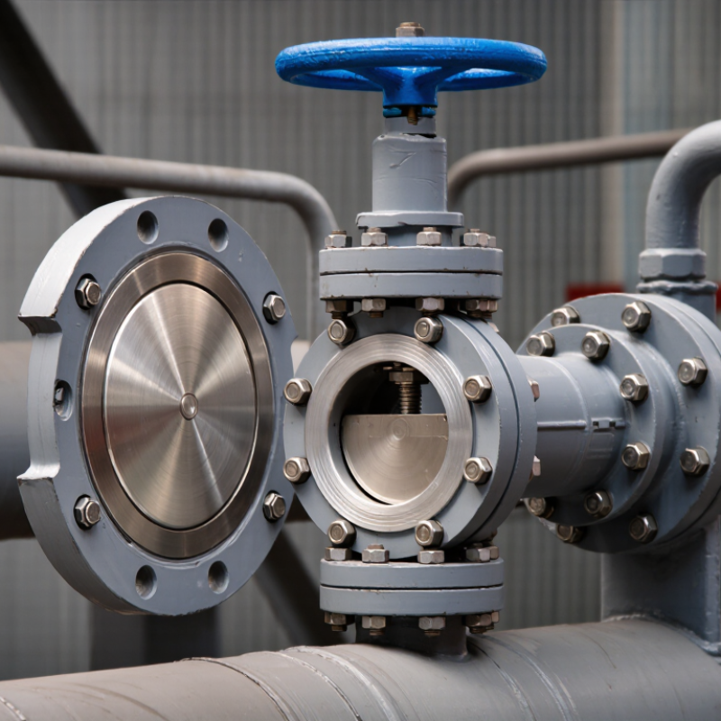
A butterfly valve is a compact flow-control device built around a 90° quarter-turn movement. Inside its body, a circular disc sits across the pipe and rotates on a stem. Turn the stem a quarter turn, and the disc moves from open to closed. At full opening, the disc aligns with the flowing medium. At closing, it faces the flow and blocks the passage. That simple motion is its main advantage. Not quite effortless.
In practical installations, operators often use a lever for smaller valves and a geared actuator for larger ones. The valve does more than start or stop flow. Partial disc rotation can throttle flow, although accurate regulation depends on valve design, pressure, and fluid conditions. A partly open disc creates turbulence, noise, and pressure loss. Field experience shows that a quick quarter-turn can solve an access problem, yet poor positioning may cause unwanted vibration. It is not always the best throttling choice.
Selection requires checking pipe size, temperature, pressure, corrosion risk, and sealing material. The disc and seat must suit the medium, especially when solids or abrasive particles are present. Before operation, inspect flange alignment and confirm the disc can rotate freely. A small installation error matters. For dependable service, operators should cycle the valve gradually and monitor leakage, torque, and downstream pressure. The mechanism looks simple, but real systems rarely are.

A butterfly valve controls flow with a circular disc mounted inside the body. The stem turns the disc, usually through a quarter-turn movement. When the disc aligns with the pipe, fluid passes through with limited obstruction. When it rotates across the passage, the valve closes. The seat presses around the disc edge and helps prevent leakage. It looks simple. The design is not careless.
The body connects the valve to the pipeline and carries mechanical loads. The disc must resist pressure, erosion, and repeated movement. The stem transfers torque from the handle, gearbox, or actuator. A damaged stem can create poor alignment and uneven sealing. In field inspections, seat wear often appears first near the disc edges. That small detail matters. Clean installation matters too.
Butterfly valves are commonly specified from DN25 to DN1200. DN25 suits compact utility lines, while DN1200 serves large water, air, and process pipelines. Larger sizes may need a gearbox or actuator because disc torque increases with pressure and diameter. Wafer, lug, and flanged bodies suit different connection requirements. Engineers should check pressure rating, temperature, medium, seat material, and operating frequency. Size alone is not enough. A valve that fits the pipe may still be poorly selected. This is where practical judgment remains necessary.
A butterfly valve regulates liquid or gas flow with a circular disc mounted inside a pipeline. The disc connects to a stem, which turns it around its central axis. When the disc faces the flow, the passage remains mostly open. When it rotates across the pipe, it blocks movement.
Its operation is simple, but the details matter. A quarter-turn actuator can rotate the disc from open to closed in about 90 degrees. At an intermediate angle, the disc narrows the available passage and reduces flow. This makes the valve useful for isolation and basic flow control. However, throttling can create turbulence, vibration, and pressure loss. Pipe size, fluid speed, and disc position all influence performance. In real installations, the ideal angle is not always obvious. Field readings may differ from design estimates.
Tips: Check the disc, stem, and seals during maintenance. Look for unusual noise, slow movement, or visible leakage. Confirm that the valve matches the fluid, temperature, and pressure conditions. Avoid forcing a stiff actuator. That can damage internal parts. A clear operating record also helps technicians identify gradual changes before they become serious.
A butterfly valve controls flow with a circular disc mounted on a rotating shaft. Turning the shaft a quarter turn moves the disc from parallel to perpendicular with the pipeline. This compact design suits water, air, chemicals, and many industrial services. Its real performance depends on pressure, temperature, sealing material, and installation quality.
Pressure ratings usually range from PN6 to PN40, but they are not universal working limits. A PN16 valve may handle 16 bar under reference conditions, often near room temperature. Higher temperatures can reduce its allowable pressure. The valve body, disc, shaft, and seat must also tolerate the medium. Ductile iron can suit general water service, while stainless steel offers better resistance against many corrosive fluids. EPDM, NBR, and PTFE seats behave differently with heat and chemicals. Compatibility charts matter. Guessing here is expensive.
A practical selection checks pressure, temperature, pipe size, flow direction, and cycling frequency. I have seen valves fail early because the seat material was chosen for pressure, not chemical exposure. The rating plate alone can mislead.
Tips: Confirm the complete pressure-temperature curve before ordering. Check whether PN6, PN10, PN16, PN25, or PN40 matches the flange standard. Leave room for thermal expansion. Inspect the disc clearance before installation. A small alignment error can damage the seat. Also, recheck the medium’s concentration and temperature during real operation, because laboratory assumptions may be too optimistic.
What Is a Butterfly Valve and How Does It Work?
A butterfly valve controls flow with a circular disc mounted on a rotating shaft. Turning the shaft aligns the disc with the pipe or places it across the passage. This compact design suits water, air, chemical, and process piping. Yet simple operation does not mean simple selection. Disc clearance, seat condition, shaft alignment, and pressure rating can affect service life.
API 609 provides a recognized design framework for butterfly valves. It addresses construction, materials, dimensions, pressure-temperature ratings, and required examinations. A valve built to this standard should match the intended line class and operating conditions. However, API 609 compliance alone does not prove acceptable shutoff performance. ISO 5208 focuses on pressure testing and leakage classification. The specified leakage rate matters. “Tight” is not always the same as “zero leakage.”
Tips: Confirm the valve type, test direction, medium, pressure, and temperature before ordering. Check the ISO 5208 leakage rate on the inspection record. A clean certificate can still hide a poor field installation. Uneven flange bolts may distort the seat. Small alignment errors can become expensive failures. Practical review is essential. The best specification includes materials, testing conditions, actuator requirements, and service history. One overlooked detail remains common: operators often judge a valve by easy movement, while internal sealing damage may already exist.
| Data Dimension | Reference or Topic | Technical Description | Typical or Specified Information |
|---|---|---|---|
| Valve Definition | Butterfly Valve | A quarter-turn valve that controls fluid flow with a circular disc mounted on a shaft. The disc rotates inside the flow passage to open, throttle, or shut off the line. | Disc rotation: approximately 90° from fully open to fully closed |
| Operating Principle | Rotary Disc and Shaft | When the shaft turns the disc parallel to the flow direction, the passage is substantially open. When the disc turns across the passage, it blocks the flow and the seat provides shut-off sealing. | Open position: low flow obstruction Closed position: disc contacts or compresses the seat |
| Main Components | Valve Construction | The principal parts are the body, disc, stem or shaft, seat, and operating mechanism. Depending on the design, the stem may be centered or offset from the disc and seat. | Body, disc, shaft, seat, actuator, position indicator |
| Common Designs | Concentric and Offset Types | Concentric designs place the shaft along the centerline of the disc and seat. Offset designs move the shaft away from one or more centerlines to reduce seat contact during operation and support lower-friction movement. | Concentric: general-purpose service Double-offset or triple-offset: reduced rubbing and higher-temperature applications |
| Flow Control | Isolation and Throttling | Butterfly valves are widely used for on/off isolation and can also regulate flow when the valve, actuator, and process conditions are suitable. Throttling performance depends on disc geometry, pressure drop, and control requirements. | Suitable for quarter-turn isolation Throttling capability varies by design and service |
| Actuation | Manual or Powered Operation | Operation may be provided by a hand lever, gearbox, pneumatic actuator, electric actuator, or hydraulic actuator. Actuator sizing must account for breakaway torque, running torque, shut-off torque, and safety factors. | Manual: lever or gearbox Automatic: pneumatic, electric, or hydraulic |
| Design Standard | API 609 | API 609 covers butterfly valves used in petroleum, petrochemical, and natural gas industries. It addresses valve types, pressure-temperature ratings, materials, dimensions, design requirements, inspection, and testing requirements for applicable valve constructions. | Covers wafer, lug, and flanged configurations depending on the applicable design category and edition |
| API 609 Valve Categories | Category A and Category B | Category A generally refers to resilient-seated butterfly valves, while Category B generally refers to high-performance butterfly valves with a seat arrangement intended for more demanding pressure, temperature, or service conditions. | Category A: resilient seat Category B: high-performance seat design |
| Pressure Rating | API 609 and Applicable Piping Class | The allowable pressure and temperature are determined by the valve design, body and trim materials, seat material, and the applicable pressure class. The pressure rating must be checked at the intended operating temperature. | Common flange classes include Class 150 and Class 300; actual limits depend on construction and materials |
| Leakage Testing | ISO 5208 | ISO 5208 specifies production pressure testing for industrial valves, including shell strength testing and closure tightness testing. The test method, test fluid, test pressure, duration, and acceptance criteria should be stated in the purchase or inspection specification. | Shell test: verifies pressure boundary integrity Closure test: verifies seat tightness |
| Leakage Rate | ISO 5208 Rate Designations | ISO 5208 defines leakage-rate designations rather than assuming that every valve has the same allowable leakage. The selected rate must be matched to the valve type, seat material, service, and project requirement. | Examples include Rate A, Rate AA, Rate B, Rate C, Rate CC, Rate D, Rate E, Rate EE, Rate F, and Rate G |
| Seat Material | Resilient or Metal Seat | Resilient seats can provide tight shut-off across a broad range of general services but have temperature and chemical compatibility limits. Metal seats are selected for higher-temperature, abrasive, or severe-service applications where permitted by the design. | Common resilient materials: EPDM, NBR, PTFE Metal seat: selected for temperature and service conditions |
| Installation Style | Wafer, Lug, and Flanged | Wafer valves are clamped between flanges. Lug valves use threaded or tapped lugs and may permit end-of-line service when specifically designed for it. Flanged valves have integral flange ends for bolted connection. | Selection depends on piping layout, maintenance needs, pressure class, and end-of-line requirements |
| Advantages | Compact Quarter-Turn Design | Butterfly valves are generally compact, lightweight, and economical for large nominal pipe sizes. They require less installation space than many multi-turn valve types and can be automated with relatively simple quarter-turn actuators. | Low weight, compact face-to-face length, fast operation, suitable for large bore piping |
| Selection Factors | Application Engineering | Selection should consider fluid composition, pressure, temperature, flow velocity, cavitation risk, solids content, corrosion, fire-safety requirements, emission control, actuator torque, installation orientation, and required leakage rate. | Confirm materials, pressure-temperature rating, end connection, seat design, actuation, and test requirements before purchase |
Technical note: API 609 addresses butterfly-valve design and related requirements, while ISO 5208 addresses industrial-valve pressure and closure testing. The exact edition, pressure class, material combination, test procedure, and acceptance rate should be specified for each project.